Machinists and tool and die makers must have a high school diploma or equivalent.
How to Become a Machinist or Tool and Die Maker
There are many different ways to become a
machinist or tool and die maker. Machinists train in apprenticeship
programs, vocational schools, or community or technical colleges, or on
the job. To become a fully trained tool and die maker takes several
years of technical instruction, as well as on-the-job training. Good
math, problem-solving, and computer skills are important. A high school
diploma is necessary.
Education
Machinists
and tool and die makers must have a high school diploma or equivalent.
In high school, students should take math courses, especially
trigonometry and geometry. They also should take courses in blueprint
reading, metalworking, and drafting, if available.
Some advanced
positions, such as those in the aircraft manufacturing industry, require
the use of advanced applied calculus and physics. The increasing use of
computer-controlled machinery requires machinists and tool and die
makers to have basic computer skills before entering a training program.
Some
community colleges and technical schools have 2-year programs that
train students to become machinists. These programs usually teach design
and blueprint reading, how to use a variety of welding and cutting
tools, and the programming and function of computer-numerically
controlled (CNC) machines.
Training
Apprenticeship
programs, typically sponsored by a manufacturer, are an excellent way
to become a machinist or tool and die maker, but they are often hard to
get into. Apprentices usually must have a high school diploma or
equivalent, and most have taken algebra and trigonometry classes.
Apprenticeship
programs consist of paid shop training and related technical
instruction lasting several years. Apprenticeship classes often are
taught in cooperation with local community colleges and
vocational–technical schools.
A growing number of machinists and
tool and die makers receive their technical training from community and
technical colleges. In this setting, employees learn while employed by a
manufacturer that supports the employee's training goals and provides
the needed on-the-job training.
Apprentices usually work 40 hours
per week and receive technical instruction during evenings. Trainees
often begin as machine operators and gradually take on more difficult
assignments. Machinists and tool and die makers must have good computer
skills to work with CAD/CAM technology, CNC machine tools, and
computerized measuring machines. Some machinists become tool and die
makers.
Even after completing a formal training program, tool and die makers still need years of experience to become highly skilled.
Licenses, Certifications, and Registrations
To
boost the skill level of machinists and tool and die makers and to
create a more uniform standard of competency, a number of training
facilities, state apprenticeship boards, and colleges offer
certification programs. The Right Skills Now initiative, for example, is an industry-driven program that aims to align education pathways with career pathways.
Completing
a recognized certification program provides machinists and tool and die
makers with better job opportunities and helps employers judge the
abilities of new hires.
Journey-level certification is available
from state apprenticeship boards after completing an apprenticeship.
Many employers recognize this certification, and it often leads to
better job opportunities.
Important Qualities
Analytical skills.
Machinists and tool and die makers must understand highly technical
electronic and written blueprints, models, and specifications, so they
can craft precision tools and metal parts.
Manual dexterity.
The work of machinists and tool and die makers must be highly accurate.
For example, machining parts may demand accuracy of .0001 inch, which
requires workers’ precision, concentration, and dexterity.
Math and computer skills.
Workers must have good math and computer skills to work with CAD/CAM
technology, CNC machine tools, and computerized measuring machines.
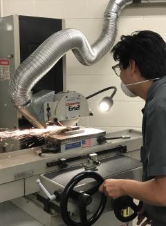
Mechanical skills.
Machinists and tool and die makers must be mechanically inclined. They
operate milling machines, lathes, grinders, laser and water cutting
machines, wire electrical discharge machines, and other machine tools.
They also may use a variety of hand tools and power tools.
Physical stamina.
The ability to endure long periods of standing and performing
repetitious movements is important for machinists and tool and die
makers.
Technical skills. Machinists and
tool and die makers must understand computerized measuring machines and
metalworking processes, such as stock removal, chip control, and heat
treating and plating.

