Tuesday, February 26, 2013

How to Become a Tool and Die Maker

Tool and die makers are at the top of the ladder in the metalworking trades. They are very versatile in using their hands for creating parts as well as machines to produce high precision parts. Their abilities go beyond that of the typical machinist. They are capable of designing and fabricating tools with no supervision. With these skills, tool and die makers are a tremendous asset in any manufacturing facility.


Master basic math. Understand addition, subtraction, and division. A little shop trigonometry is good for calculating bolt circles and finding the length of triangles. Some basic algebra can also be handy for applying handbook formulas.

Learn computer drafting. Suitable skills are included in vocational and technical schools' machining programs. Learn to create and interpret mechanical drawings.

Enter an apprenticeship program at a tool and die shop while in high school if possible. As an apprentice, you will do simple tasks like drilling, deburring, and sweeping in the beginning. The tasks will become more challenging as time goes on. You will learn the lathe, mill and surface grinder. Apprenticeships typically last 2 to 4 years.

Study machine tool technology at a good vocational trade school. Programs vary from school to school. Make sure you are studying at one that has various machines to learn from. A wire EDM (electrostatic discharge machining) tool would be nice. Also, make sure they have good CNC (computer numerically controlled) programming courses. Try to get hands-on experience in a shop rather than studying only in a classroom. The heart of your education will be in the types of projects you will be making in the course. A typical machine tool technology program will last two years.

Get a copy of the Machinery Handbook and refer to it often. This is an excellent reference for answering any machining problem.

Buy a set of good high quality precision tools like 1-2-3 inch micrometers, and a square set, along with a 7- or 11-drawer machinists toolbox. An electronic caliper is a plus also.


Try to stay away from generic tools because these seem to be less durable. Instead, invest in high quality tools like Starrett and Mitutoyo, top names in the trade.
If money is tight, obtain tools gradually, as you need them, over time, until you have your own set. Get the ones you need most first.


Try to stay away from generic tools because these seem to be less durable. Instead, invest in high quality tools like Starrett and Mitutoyo, top names in the trade.
If money is tight, obtain tools gradually, as you need them, over time, until you have your own set. Get the ones you need most first.

If you want to further your career in the tool and die trade, you may want to move into supervision or teaching. A Bachelor's degree in almost any field along with tool and die experience would be very beneficial in obtaining a supervisor's job in manufacturing and/or teaching.

Tool and Die Making


Tool and die making,  the industrial art of manufacturing stamping dies, plastics molds, and jigs and fixtures to be used in the mass production of solid objects.

The fabrication of pressworking dies constitutes the major part of the work done in tool and die shops. Most pressworking dies are utilized in the fabrication of sheet-metal parts that range in size from the finger stop on a dial telephone to the panels of an automobile body. Each pressworking die consists of two sections, called punch and die, or male and female. Both sections are mounted firmly in an electrically or hydraulically driven press. In a working cycle the press ram, on which the male section is mounted, descends into the fixed female section. Any metal interposed between the sections is cut or shaped to a prescribed form. Like the dies, the presses range in size from extremely small to gigantic. A bench press is often small enough to be picked up manually; but the press that stamps out the roof of a car is generally about three stories high and capable of exerting tons of force.

The tooling involved in plastic molding is quite similar to that of stamping dies. The principal difference is that stamping requires force, while molding does not. In plastic molding, two units are required whose design is such that, when brought together, they make up a system of closed cavities linked to a central orifice. Liquid plastic is forced through the orifice and into the cavities, or molds, and when the plastic solidifies, the molds open and the finished parts are ejected.

The development of modern tools and dies can be traced to the American inventor and manufacturer Eli Whitney, who first implemented the concept of the planned manufacturing of interchangeable parts. Each part was manufactured to prescribed dimensions with the aid of tooling, so that the highly skilled craftsmen previously required for manufacturing were no longer needed since no additional fitting or selective assembly of the parts was necessary. Whitney’s tooling consisted of templates (tool-guiding patterns) and rudimentary fixtures—the antecedents of today’s tools and dies—and he successfully demonstrated the feasibility of manufacturing interchangeable parts by mass-producing firearms for the War of 1812.

The successful introduction of interchangeable parts and the development of machine tools, both in the 19th century, brought the modern machine shop into being. Then, as now, the independent machine shop was called a job shop, which meant that it had no product of its own but served large industrial facilities by fabricating tooling, machines, and machinepart replacements. Eventually, some machine shops began to specialize in tooling to the exclusion of other work.

The development of the power press gave rise to a demand for another form of tooling, the press die, the function of which is to cut and form sheet metal into predetermined shapes and configurations. The work of fabricating press dies is similar to, but not identical with, that of producing jigs, fixtures, and other tooling, which led to many of the specialized machine shops labeling themselves tool and die shops. The 20th-century developments of die casting and injection molding have brought about the demand for still other forms of tooling—the dies used in die casting and plastic molding. The making of these tools has also been taken over by the tool and die shops.

In the second half of the 20th century, however, the traditional tool and die shop was gradually replaced by specialized job shops that produce only one form of tooling. This trend can be attributed to the growing sophistication of tooling, for shops with the skills and equipment necessary to fabricate one form of tooling are seldom equipped for another. Even the single form of toolmaking called diemaking is becoming specialized; some shops now limit themselves to dies for special applications, such as automotive body dies.

Thursday, February 14, 2013

Types of Die Cutting Operations


A major advantage of die cutting is its versatility as a fabrication method. Since the process depends upon the shape and configuration of an interchangeable die, manufacturers can perform multiple operations using a single cutting machine by replacing the die itself. Specialized dies may be used for specific projects, such as those involving bending, coining, or curling. Generally, the name of the operation is signified by the type of die used in it.


Bending
Bending is the process of deforming a base material through pressure from a die. For example, if the product requires an “L” bracket design, the die descends and curves the length of material into a 90-degree angle.

Blanking
Blanking is a way of cutting flat material by trimming it from its exterior edge. The blanking die usually compresses uniformly, creating a precise degree of flatness.

Broaching
A broaching die can be a useful option for shaping material that is too thick or hard to be cut by other means. This die employs multiple rows of successively larger cutting teeth to trim away material quickly and efficiently.

Bulging
A bulging fluid die uses water or oil as a medium for expanding a part, while a bulging rubber die harnesses a pressurized rubber block to deform a work piece. Bulging can be used for expanding pipes or other cylindrical parts.


Coining
Coining is a type of stamping procedure used to punch circular holes through a material (usually metal). The cut is made via pressurized force clamping a punch and die. This process can result in highly intricate or precise product features.

Curling
A curling die rolls or bends material into a curved shape. Common uses for curling include the fabrication of door hinges or the removal of sharp edges on sheet metal parts. Curling can also improve material stiffness.

Cut Off
When excess material needs to be trimmed from a finished part, the process is usually performed by a cut off die. These dies are also used to cut or shorten a piece of material by a predetermined length to prepare it for further tooling or machining processes..

Drawing
Drawing is a method of pulling material to a designated length, resulting in a thinner, longer work piece. Products such as tubing, bars, or wires are often fabricated through drawing.

Extrusion
Extrusion applies a high degree of pressure to force material between a punch and an extrusion die, which cuts it into shape. Unlike coining, the material only takes on the characteristics of the die, rather than those of the punch and die in combination.

Forming
This process bends the base material or blank along a curved surface, and is often used in conjunction with drawing to fabricate rounded cylindrical parts.

Roll Forming
This method uses a series of deforming rolls set at precise intervals to shape a continuous stream of stock as it rolls through the machinery. Roll forming is particularly effective for fabricating lengthy materials and producing specific cross-sectional designs.

Swaging
Swaging is used to create a "necking down" feature, like the tapered end of a bullet casing. It can be performed in either a cold or hot process, and, unlike bulging, uses a pressurized die to compress rather than expand a cylindrical part.


What is Die Cutting


Die cutting is a manufacturing process used to generate large numbers of the same shape from a material such as wood, plastic, metal, or fabric. The die cut shapes are sometimes called “blanks,” because they are usually finished and decorated before being sold. The process is widely used on an assortment of materials all over the world, and many manufactured products contain several die cut components, often assembled together in a series of steps to create a finished product.


Sharp specially shaped blades are used in die cutting. The blade is bent into the desired shape and mounted to a strong backing. The result is known as a die. The material being cut is placed on a flat surface with a supportive backing, and the die is pressed onto the material to cut it. Depending on what is being made, a single die might cut one piece of material, or it might be designed to slice through multiple layers, generating a stack of blanks.

Many consumers find it helpful to consider a cookie cutter when thinking about die cutting. The cookie cutter is a type of die which is capable of cutting out a potentially infinite amount of blanks. Each blank will be exactly the same shape and size, meaning that the blanks can be cooked uniformly together and decorated at will for individuality. The alternative is cutting out each cookie by hand, a painstaking process which would result in irregular final products.

Creating dies is meticulous work. The die must be designed so that it efficiently cuts the desired material with minimal waste. Most factories which use die cutting as part of their manufacturing process have techniques for recycling material left over from die cutting, but they want to avoid excess if possible. Often, multiple dies are fitted together on one mount, nestled with each other for maximum efficiency. Material left over from the die cutting process may be melted down and reused, or reworked into other components.


Common examples of die cut items include keys, paper products, and flat plastic pieces which can be snapped together. Die cutting is limited, because it can only really be used to produce flat objects. For more dimensional shapes, other manufacturing techniques such as molds need to employed. Dies can also range widely in size from cookie cutters to massive machines designed to cut out ship components. With large dies, it is important to observe safety precautions while die cutting, as an industrial die designed to slice through metal can also remove a limb without difficulty.

A Guide to Die Cutting


Die cutting is an important part of the manufacturing industry that involves creating a blade in a specific shape and then using that blade to punch out specific shapes from pre-selected material. The best way to really describe the process is to think about how cookie cutters work.
Here’s how die cutting works:
  1. The blade is bent into the proper shape for the job, thus creating the die.
  2. The die is mounted to backing in preparation for cutting.
  3. Workers place the material that the shapes will be cut from on a flat surface that has plenty of support. They often put several lays of the material on top of each other so that multiple shapes can be cut out in one step.
  4. The machine presses the die down into the material, cutting the shape out of all the layers of the material.
  5. The blanks that have been cut from the material are moved off to be finished.
A number of different materials can be cut with a die, including wood, paper, metal, plastic, foam, cork, and more. The applications for this type of are endless. In manufacturing, almost any kind of product can be made via the die cutting process. Also the dies that are used can be of almost any size, even large enough to cut out components for automobiles or large machinery.

Companies looking for a manufacturer to handle their die cutting should consider a number of things before making a selection. For example, you should ask about the process for professionally laying out the dies and burning them. Also ask how the knifing is done so that you can make sure the company is using the latest technology.

Die cutting has been around for many years, and there is no sign of the process going anywhere. In fact, constant innovations have made the process simpler and faster than ever before. This is the standard for mass production of some items, so it is important that you have a trusted company handling all of your die cutting.

Cutting Terminology


Tools used in blanking, punching and trimming operations consist of a punch and die. The terms “punch” and “die” often are misinterpreted, primarily because they have double meanings.

For example, a complete stamping tool often is referred to as a “die,” and the individual that built it, a “die-maker.” The die is comprised of two main halves: the upper die, often referred to as the punch; and the lower die, often referred to as the die. This is pretty clear until you consider that “punch” may also refer to one or more male forming or piercing components, which may be mounted to either the upper punch shoe or the lower die shoe. Now when the die gets mounted to the punch and the punch is mounted to the die it can become very confusing.
Another source of confusion is the terminology we use for cutting operations. What is the difference between piercing and punching, trimming and parting, or slitting and shearing? Does any clear definition exist?
Definitions for these various cutting operations are compiled here from a number of sources, but mainly: Modern Industrial Die Design by E.A. Nowolinski (1947), Techniques of Pressworking Sheet Metal, D.F. Eary and E.A. Reed (1974), Automotive Sheet Metal Stamping and Formability (AISI Report AU-89) by S.P. Keeler (1989) and Advanced High Strength Steel Guidelines, AISI Committee on Automotive Applications (2003). Why these materials? All of them can be considered significant works of their time and they use cutting terminology consistently in the following manner:

Shearing is performed by a cutting blade acting upon a workpiece placed between a stationary lower cutting blade and a movable upper blade. To be classified as a shearing operation, the cutting action must be along a straight line.

Slitting is the cutting of lengths of sheetmetal into narrower lengths by use of one or more pairs of circular knives. Spacers on the slitter arbors maintain the proper blade location for the desired width. The cutting up of a wide coil (master coil) into two or more narrower coils is called slitting.
Piercing Operation
Piercing Operation


Blanking involves cutting actions to produce a complete or enclosed shape. The blank is the piece retained for further processing. The shape may be composed of any combination of straight and curved line segments. Developed or contoured blanks used in drawing and forming operations oftentimes are generated by blanking operations. In blanking operations, offal or skeleton webs are produced. These materials often are cut up into smaller pieces and discarded as scrap.

Perforating (Punching) is generally used to describe all die-cut holes, regardless of their size or shape. In Techniques in Pressworking Sheet Metal, Eary and Reed differentiate between punching and piercing by emphasizing the fact that a slug is produced in punching operations but not in piercing work.

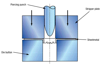
Piercing often is used interchangeably with punching and perforating operations. However, piercing operations are frequently (but not always) defined as “forming a hole in sheetmetal with a pointed punch with no metal fallout (slug).” The illustration depicts a piercing operation fitting this description.

Lancing makes an opening without completely separating the cut piece from the body of the metal sheet, such as for louvers. Lancing frequently is combined with bending to form tabs. No slug or scrap is produced in lancing operations.

Trimming removes unwanted material from the finished part that was required for some previous stamping operation such as drawing or stretch forming. Trimming is frequently performed on the earing zone on the top of a deep-drawn cup in order to produce a round flange. Trimming operations produce discarded offal or scrap.

Parting operations are used to separate two stampings that were formed together (usually to make two parts at one time or to balance the draw operation of a nonsymmetrical part). Parting also is an operation that involves two cutoff operations to produce contoured blanks from strip. Scrap is produced in the parting operation.

Shaving is performed on a cut edge to square it up. In general practice, five percent of the thickness of the blank is allowed for shaving.

Fineblanking is a specialized process often employed if the blank edge has an important function to perform or when square edges and no die-roll are prescribed.

Basic Metal Stamping Die Components and Terminology


The Language of Mechanical Engineering

There's a sort of pseudo-language that's developed in the metal stamping industry. For the layperson, that hasn't been enlightened as to how sheet metal parts are made, listening to someone talk about it can be like listening to someone speaking a foreign language.

This guide was written to help those that want to know what engineers and factory workers are talking about when they are discussing sheet metal stamping and the machines that perform the processes of stamping, forming, trimming, flanging, piercing, and restriking sheet metal.
Die engineering is one of those crafts that takes years to understand fully. At least a crude knowledge of metallurgy, pressure systems, steel machining, and iron casting are all tools that die designers and builders possess.

Computer technology has given the layperson a way to view three dimensional models of stamping presses and dies. These virtual design programs are crucial in allowing others to follow a die through the various phases of its design and build. But, if you have no idea what components you are looking at or what purpose they serve, you'll have trouble following anyone's explanations of the machine, simply because so many of the names and words used in mechanical engineering aren't known to the person who hasn't had prolonged exposure to the metal stamping industry.

For an even more basic introduction to sheet metal stamping in the automotive industry, please read Stamping Dies: A Basic Explanation of Metal Stamping Dies. That guide is designed to help people understand the most basic concepts of how an automobile part made of sheet metal goes from concept to production and acts as an educational lead-in to this article.

An illustration showing what press stroke is.  Press stroke is key information designers use to set up a part load height and determines the size of the die set mounted to the press.


An illustration showing what press stroke is. Press stroke is key information designers use to set up a part load height and determines the size of the die set mounted to the press.

Basic Die Design and Build Terminology

The following terms are in order of usefulness; they are ordered to help someone unfamiliar with mechanical die types and their application as tools to make stamped metal parts.

Stamping Press: This is the machine that a finished die set attaches to. The bottom of a press, or the base, is stationary. The upper ram travels up and down, and provides the pressure required to form or hold the metal place onto the lower half of the die, which is mounted to the stationary base. The upper die member is mounted to the ram, thus traveling up and down with it.

Press Stroke: The ram of a press proceeds down until the upper die member is closed upon the lower die member. The ram then returns up, opening the die and allowing the finished part to be removed. A new blank is then placed into the die. Each up and down cycle is accomplished to the same specifications dependent on the type of press. The distance the ram travels either up or down is the press stroke.
Larger presses typically have greater press stroke distance. Another important factor of press stroke is strokes per minute. Different presses have different speed variations, and two factors, press stroke distance and press strokes per minute, are considered carefully before die engineers start work on the dies that'll be mounted to the press carriage and ram.

Die Size: These dimensions generally refer to the upper and lower plates the remainer of the die's components are mounted to. These are either die sets made of steel or cast iron shoes. Iron is cheaper than steel so, if a large die is required, more than likely it'll be made of iron. Smaller die sets are made of steel and often sold as complete die sets with guide pins and mounting slots or holes provided. The dimensions of a die include overall (o.a.) die size and die set size. If an upper iron shoe is 50 mm thick and 1200 mm long and 800mm long the dimensions would look like this: 50 x 1200 x 800. Cast dies can easily be designed to any size whereas steel die sets are sold in various sizes, choosing the right one can sometimes prove a challenge.

Castings: When a decision has been made to design a die from iron, the parts of the die are called castings. This does not include standard items like die punches or safety blocks, which are normally made from steel. Iron castings are unfinished metal that can be machined at various locations where a clean surface is required (i.e. a mounting surface).
Designing castings requires the engineer to take in account weight, wall strength, core size, and cost. Once a casting design is approved, it's pulled, or separated, from the overall design and given its own computer file. This file is sent to a foundry where iron is poured to the exact specifications given to them by the design source. When the iron cools, a rough cast of the three dimensional design is ready for further work by machinists.

Die Detail: These are normally castings pulled from the overall design, as described above. But, they can include steel components. Whenever a drawing or 3D model will help builders better see, or comprehend, a design, a build company might ask for separate layers or files that will allow them to look at any major die component separately. An upper die pad, for example, would be cast and machined from material (files, blueprints) that showed it not only as it set in the die, but separately, too.
An end cutter is mounted to a milling machine so that a pocket can be machined, or milled, into a block of steel.

Milling and Machining: The act of finishing a surface is called machining. It's often accomplished with a spinning metal cutter, called a mill. Mills can be used to cut pockets into iron or steel, create finished surfaces to tight specifications, and follow paths programmed into its computer that allow them to machine large surfaces for hours without stopping.
In the figure above note the rounded corners of the pocket being machined. Unless there is a run-out - a way for the path of the cutter to be unobstructed as it is removed or moving onto its next operation - the corners will be rounded to the same radius as the cutter. These tools can't make square corners, but there are wire burning tools and other options for doing so.

Core Design: This refers to the practice design engineers use to lighten metal. That is, a solid block of iron could be cored (lightened by removing some of the iron), so long as it doesn't compromise the iron's strength inside the die. The two benefits of designing a die with an intelligent core plan (many times to coring standards provided by the entity that requested the part) are iron cost efficiency and die weight sensibility.

Blank Drawing: This is the operation performed by draw dies. These dies are normally the first or second die in any die lineup. An unformed sheet metal blank is loaded into the die and formed to specifications provided in the part data file. Draw dies use pressure to form metal. A floating lower pad, powered by a pressure system below it, is an integral part of any draw die. This pad can be used to form the metal against the upper punch or it can be used as a 'ring' to grip the metal as the punch comes down and forms it.

Trim Die: This type of die is designed with a focus on trimming unwanted metal off a part. Trim dies can be implemented to trim out large holes, like window openings. Trimming to a finished trim line is sometimes accomplished with more than one trim die in the lineup. Designers will do their best to get all major trimming operations done in one die, but sometimes it just isn't possible.

There are three basic trim types:
Rough Trimming: Cutting away material to gain efficiency or access in the next operation, the final trim.
Final Trimming: This is the operation where the part is being trimmed to its final shape.
Interior Trimming: Normally more involved and requiring a trim steel layout plan, this is the act of trimming out openings that are located inside the final trim line.

Trim Steels: These manageable steel components have a mounting surface and a trim blade. The blades mounted on an upper die or cam act like the top of a pair of scissors. When they are brought down upon the metal, they meet a lower steel that act as the lower jaw of a pair of scissors. The steels are entered slightly into the metal, enough to bypass its metal thickness. The sheet metal that falls away from the trim line after trimming is called scrap.
A trim steel, mounted ultimately to the upper ram of a stamping press, travels downward until it bypasses the sheet metal blank far enough to separate the scrap from the desired part.

Pierce Equipment: When smaller openings, like round or square holes, are required in a panel, a die punch is used (mounted in a die retainer, which is in turn mounted to a closing die surface). These hardened steel punches can be sharpened so that a single punch can survive the entire stamping procedure, sometimes tens of thousands of strokes. Pierce equipment normally refers to the male punch, the female die button, and the mounting retainers.

Die Cam: This is a mechanical device (see diagram below) that allows a die operation to be performed in a manner other than straight up and down. An angular surface can be machined onto a die's surface to accommodate a cam slide, the half of the cam that can actually move in a more horizontal manner. The cam driver's angular surface closes upon the cam slide's angular surface, causing the lower half to slide in a given direction. A punch, for example, mounted onto the face of cam slide can be pressed forward by the cam driver so that it punches a hole horizontally into sheet metal.

Obviously, as those that have interest in die design learn more advanced die processes, they will be exposed to more and more new terminology. Because part manufacturing requires so many people in different crafts to get involved, there's an opportunity for the more ambitious to learn not only the vocabulary in their own field, but in each of the complementary processes, too.

A well-rounded manufacturing engineer will understand the journey a sheet metal blank takes to get to finished product. The machinery built to produce these parts goes through a process just as valuable to the engineer who wishes to converse about part manufacturing on all levels.
The two large arrows at left show that the upper part of the die comes down, then its angular surface strikes the cam slide, causing it to slide to the right.


The two large arrows at left show that the upper part of the die comes down, then its angular surface strikes the cam slide, causing it to slide to the right.


Vocabulary TermDefinition
air bending A bending operation performed by using a punch to force the sheet into a die cavity without a bottom.
bed The main foundation and supporting structure upon which the operating parts of the machine are mounted and guided.
bending The shaping of sheet metal by straining the metal around a straight axis. A bending operation compresses the interior side of the bend and stretches the exterior side.
blankholder The tool in a drawing die that holds down the outer rim of the metal sheet as it is drawn into the die cavity.
blanking A shearing operation that creates a hole in sheet metal by separating an interior section. The removed piece of metal is the desired section.
bolster plate A plate that is designed to hold in place the lower die shoe. The bolster plate is attached to the top surface of the press bed.
clearance The amount of space between the outer edge of the punch and the inner edge of the die cavity. A proper amount of clearance is necessary for an effective shearing operation.
combination die Another term for a compound die. For some manufacturers, the term "combination die" implies a die that both cuts and forms the metal.
compound die A die designed to simultaneously perform more than one operation with each stroke of the press. For example, a compound die may blank and pierce in a single stroke.
die The main tool typically attached to the lower portion of the die set. The die contains a recess that provides space for the shaping or shearing of sheet metal.
die button A hardened steel tube that provides the opening for the punch during operation. During a shearing operation, the slug or blank passes through this opening.
die holder Another term used for the lower die shoe.
die retainer A hardened steel block containing machined impressions or cavities that shape the metal as the punch descends from above. The die retainer also holds the die button.
die set The collective assembly of upper and lower die shoes, guide pins and bushings, and punch and die retainers.
drawing For sheet metal, a forming operation that transforms a flat disc of stock into a hollow cup with an enclosed bottom. Drawing operations can also create boxes and more intricate shapes as well.
edge bending A bending operation performed by compressing the sheet metal between two flat dies and using a punch to bend an extended portion of the sheet over the lower die corner.
ground Machined with an abrasive to achieve a very precise dimension with excellent finish.
guide post A hardened rod positioned in the lower die shoe that fits into a bushing in the upper die shoe to guide the punch during operation.
guide post bushing A hardened steel tube that slides over the guide post and directs the upper die shoe during operation.
hardness The ability of a material to resist scratching or penetration.
lower die shoe The lower plate of a die set that supports the die retainer and die button.
matrix Another term used for the die button.
pilot A long, slender punch with a rounded tip used to position the metal sheet by entering a previously formed hole. Pilots are longer so that they enter the sheet before other tools form the metal.
plain-carbon steel A basic grade of steel, which contains less than 3 percent of elements other than iron and carbon.
press brake A type of press with an open frame and very wide bed. Press brakes are often used for bending operations, and they are typically manually operated.
progressive die A die containing a series of stations that perform one press operation after another in series. A progressive die gradually forms a part as it moves through the die, and the last operation separates the part.
punch The tool typically attached to the upper portion of the die set that shapes or penetrates the sheet metal.
punch holder Another term for the upper die shoe.
punch press A machine with a stationary base and an upper ram that moves along a vertical axis to shear, bend, or form sheet metal.
punch retainer The device used to mount the punch on the upper die shoe.
punching A shearing operation that creates an open hole in sheet metal by separating an interior section. The removed metal section is discarded scrap.
ram The main upper portion of the press that slides up and down within the press frame. The upper die shoe is attached to the ram.
slug The discarded section of scrap produced by a punching operation.
station A position within a progressive die where a punch and die perform a single metalworking operation. Progressive dies consist of a series of stations.
stripper A plate designed to remove sheet metal stock from the punch as it pulls away from the die during the operation.
stroke The distance marked by the farthest ends of reciprocating vertical movement of the press ram.
tool steel A type of steel designed for excellent wear resistance, toughness, and strength. Tool steels are typically variations of high-carbon steels.
toughness The ability of a metal to absorb energy without breaking or fracturing.
upper die shoe The upper plate of a die set that secures the punch retainer.
V-bending A bending operation performed by compressing the sheet metal between a V-shaped punch and die.
wiping die The tool used in an edge bending operation that provides the corner over which the extended portion of sheet metal is bent.


Forging operations


Forging operations
1: Drawing:
This is the operation in which metal gets elongated with a reduction in the cross sedation area. For this, a force is to be applied in a direction perpendiaulant to the length axis.

2:Up setting:
This is applied to increase the cross seat ional area of the stock at the expanse of the length. To achieve the length of upsetting force is applied in a direction parallel to the length axis, For example forming of a bolt head.  


3:Fullering:
It a similar to material cross-section is decreased and length increased. To do this; the bottom fuller is kept in angle hole with the heated stock over the fuller .the top fuller is then kept above the stock and then with the sledge hammer, and the force is applied on the top fuller.  
                           
4:Edging:
It is a process in which the metal piece is displaced to the desired shape by striking between two dies edging is frequently as primary drop forging operation.


5:Bending:
Bending is very common forging operation. It is an operation to give a turn to metal rod or plate. This is required for those which have bends shapes.


6:Punching:
It is a process of producing holes in motel plate is placed over the hollow cylindrical die. By pressing the punch over the plate the hole is made.


7:Forged welding:                                                                                                                                                       It is a process of joining two metal pieces to increase the length. By the pressing or hammering then when they are at for ging temperature.Itis performed in forging shop and hence is called forged welding.
8:Cutting:
It is a process in which a metal rod or plate cut out into two pieces, with the help of chisel and hammer, when the metal is in red hot condition.
9:Flating and setting down:
Fullering leaves a corrugated surface on the job. Even after a job is forged into shape with a hammer, the marks of the hammer remains on the upper surface of the job. To remove hammer marks and corrugation and in order to obtain a smooth surface on the job, a flatter or set hammer is used.


 10: Swaging:
Swaging is done to reduce and finish work for desire size and shape, usually either round or hexagonal. For small jobs top and bottom swage pair is employed, where as for large work swage block can be used.


Difference between Hot and Cold Working processes

Difference between Hot rolling and cold rolling processes


                   Hot rolling
             Cold rolling
1: Metal is fed to the rolls after being heated above the recrytallization temperature.
1: Metal is fed to the rolls when it is below the recrystallization temperature.
2: In general rolled metal does not shows work hardening effect.
2: The metal shows the working hardening effect after being cold rolled.
3: Co-efficient of friction between two rolls and the stock is higher, it may even caused shearing of the metal in contact with rolls.
3: Co-efficient of friction between two rolls and the stock is comparatively lower.
4: Experiment measurement are difficult to make.
4: Experiment measurement can be carried out easily in cold rolling.

5: Heavy reduction in area of the work piece can be obtained.
5: Heavy reduction is not possible.
6: Mechanical properties are improved by breaking cast structure are refining grain sizes below holes and others, similar deformation in ingot (get welded) and or removed the strength and the toughness of the job should increases.
6: Hotness increased excessive cold working greatness crackers ductility of metal reduction. Cold rolling increased the tensile strength and yield strength of the steel.
7:Rolls radius is generally larger in siz.
7: Rolls radius is smaller.
8: Very thin sections are not obtained.
8:Thin sections are obtained.
9: Hot roll surface has(metal oxide) on it , this surface finish is not good.
9: The cold rolled surface is smooth and oxide free.
10: Hot rolling is used un ferrous as well as non ferrous metals such as industries for steel , aluminum, copper , brass, bronze , alloy to change ingot into slabs.
10: Cold rolling is equally applicable to both  plain and alloys steels and non ferrous metals and their alloys.
11: Hot rolling is the father of the cold rolling.
11: Cold rolling follows the hot rolling.

Press Working Terminology


A simple cutting die used for punching and blanking operation as shown:

1: Bed:
The bed is the lower part of the press frame that serves as a table to which a
Bolster plate is mounted.
2: Bolster Plate:
This is a thick plate secured to the press bed , which is used for locating and
supporting the die assembly. It is usually 5 to 12.5 cm thick.
3: Die Set:
It is unit assembly which incorporates a lower and upper shoe, two or more guide parts and guide part bushings.
4: Die Block:
It is a block or a plate which contains a die cavity
5: Lower Shoe:
The lower shoe of the a die set is generally mounted on the bolster plate of a press. The die block is mounted on the lower shoe, also the guide post are mounted on it.
6: Punch :
This is male component of  a die assembly, which is directly or indirectly moved by and fastened to the press ram or slide.
7: Upper Shoe:
This is the upper part of the die set which contains guide post bushings.
8: Punch Plate :
The punch plate or punch retainer fits closely over the body of the punch and holds it in proper relative position.
9: Back up Plate:
Back up plate or pressure plate is placed so that intensity of pressure does
not become excessive on punch holder. The plate distributes the pressure
over a wide area and the intensity of pressure on the punch holder is reduced
to avoid crushing.
10: Stripper:
It is a plate which is used to strip the metal strip from cutting a non-cutting
Punch or die. It may also guide the sheet.