Saturday, March 23, 2013

Discusses the fundamentals of drawing and stretching


What Is Drawing?

Die Drawing process 

Figure 1


Drawing is a metal forming process in which a product is made by controlling sheet metal flow into a cavity and over a punch. The process of deep drawing means that the part must be taller than its minimum width.
Many people confuse drawing with stretching. True drawing results in very little stretching of the metal. Drawing requires metal flow, while stretching does not. It is only through the drawing process that objects such as oil pans, beer kegs, and oil filters can be made.
Drawing can be better defined as the process of displacing pre-existing surface into an alternate-shaped vessel containing nearly the same surface area. Stretching can be defined as the increase of surface area that results in a product with more surface area than the original surface area.
Drawing requires the metal to feed inward toward the punch. Very little or no metal flow takes place during stretching. However, keep in mind that because drawing does require tension to pull the metal inward, some stretching occurs during drawing.
The key in deep drawing is to limit the amount of metal stretching and thinning that take place. Items such as oil pans require significant drawing and stretching. Achieving a deep-drawn product that exhibits very little metal thinning requires extensive knowledge of sheet metal properties, drawing ratios, radii, and friction.Figure 1 shows the drawing process.

Basic Drawing Components

Die Drawing process 

Figure 2


the deep-drawing process is not directional-specific. in other words, the direction in which the drawing takes place really doesn't matter. you can draw a part up or down into a cavity. you can even draw a part vertically using cams or special vertical-motion presses.
please keep in mind that i am in no way indicating that process engineers or die designers don't pay close attention to the direction in which are drawing. drawing direction must be given careful attention because it affects the ability to move, cut, and eject the part in the die. if drawing is incorporated into a progressive die, the drawing direction also may affect the die and strip carrier design.
Figure 2 shows a section view of a very simple single-action drawing die. this die is designed to produce a round cup with a small flange. a basic drawing die consists of the following components:
1. Die set or foundation. This could be made of mild steel cast iron or aluminum. It serves as the guided foundation on which all of the metal forming sections will be mounted.
2. Draw cavity. The draw cavity represents the drawing die's female portion. Uually made from tool steel or solid carbide, it serves as the cavity in which the metal is formed.
3. Ejectors and knockouts. These pressure-loaded components serve to push or eject the part from the draw cavity. a high-pressure knockout must be timed properly so that it pushes the part out of the cavity after the die has fully separated. If the knockout is timed incorrectly, the part can be crushed during the return stroke of the press.
An alternate method to using a knockout is to use a small ejector pin and a lightweight spring. this spring must have enough force to eject the part adequately but not deform it during the press's return stroke. The pin and spring method does not require specific timing. However, keep in mind that certain part geometries require a great deal of force to eject from the cavity. in such cases, a timed high-pressure knockout may be necessary.
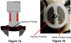
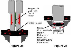
4. Air vents. Air can be trapped during drawing. This trapped air must be vented out of the tool. Not venting the air can cause defective parts, splitting, and wrinkling, as well as make it difficult to strip the drawn part from the cavity.
It is critical that both the cavity and punch contain air vents. Air vents in the cavity allow trapped air to escape during the downstroke of the press; air vents in the punch allow air to be pulled into the punch, which prevents suction during the part-stripping process.
5. Die face. The die face is the surface surrounding the cavity. it can be a flat or a contoured surface. this surface interfaces with the sheet metal and keeps it from wrinkling during the drawing process. the die face typically is made of tool steel or carbide and is highly polished in the direction of metal flow.
6. Draw punch. This component represents the male shape of the drawn part geometry. Like the cavity, it usually is made of tool steel. In most cases, it is polished to a mirrorlike surface. However, there are times when a rough surface is desired.
Die Drawing process 

Figure 3


7. Blank holder /draw pad / binder. This pressure-loaded plate, which serves to keep the metal from wrinkling during the drawing process, typically is loaded with gas springs. However, certain drawing dies can achieve the force needed to control metal flow through the use of a press cushion.
8. Pressure system. The pressure system supplies the force necessary to control metal flow. It may consist of gas, coil, hydraulic, or urethane springs. Certain drawing dies utilize a press cushion to obtain the needed pressure. A press cushion is a plate or series of vertically moving thick, flat plates mounted beneath the press's bolster plate. These plates transfer the force to the bottom of the draw pad using a cushion pin (Figure 3).
9. Equalizer block. This block functions to maintain a specific gap between the die face and the draw pad surface. It also allows for minor adjustments to be made with respect to how much pressure is being applied to the blank.

Defines slug pulling and common causes


Slug pulling is a serious problem in a stamping operation. Addressing the issue requires first understanding why the slugs are pulling.

What Is Slug Pulling?

When a pierce punch creates a hole, it also produces scrap, usually referred to as a slug. Slug pulling occurs when the slug sticks to the punch face upon withdrawal and comes out of the button, or lower matrix.
If a slug falls off the punch and onto the strip or part, it can damage the part and die. Keeping the slug down in the matrix or, better yet, completely pushing it out of the die is the desired scenario.

What Causes Slug Pulling?

Many factors contribute to slug pulling. Among them are trapped air; large cutting clearances; extremely fast piercing operations; sticky lubricants; improperly demagnetized punches; and fatigued or insufficient spring ejectors.
Slug pulling diagram
1. Trapped air/ vacuum pockets. The slug generated during the piercing process has some curvature. The curved, void areas where air is trapped, creating a vacuum action. During the perforating process, a tight seal is maintained around the punch perimeter. When the punch is withdrawn, this seal prevents the slug from coming off the punch (Figure 1a). Keep in mind that the only portion of the piercing punch that makes contact with the metal is a localized zone around the punch's outside diameter. Even punches with angularity make only localized contact with the metal (Figure 1b).
Trapped air must be allowed to escape to reduce the amount of vacuum. This is done by creating a small air vent in the center of the pierce punch, which allows the otherwise trapped air to exhaust itself from the vent hole and reduce the suction. Losing suction breaks the seal between the slug and the pierce punch and allows the slug to fall (Figure 2a).
Slug pulling diagram figure 2
When piercing punches that are too small to vent are used, other means of addressing slug pulling most likely will be necessary. Also keep in mind that addressing the trapped air probably won't solve the slug pulling issue completely, but it will certainly help.
2. Larger cutting clearances. Although using engineered or larger cutting clearances can result in much greater punch and matrix life, there is one drawback to doing so. As the clearance gets larger, compression on the slug decreases, which increases the chances of slug pulling.
When smaller cutting clearances are used during the perforating process, both the slug and metal outside the slug are forced into compression. After the slug is cut free, it decompresses and remains in the matrix. This is because the decompressed slug now has an interference or press fit into the matrix.
In simple terms, when greater cutting clearances are used, the slug will be slightly smaller than the hole in the matrix, which means it may be pulled from the matrix by the punch, resulting in slug pulling. Reducing the cutting clearance certainly can help this problem, but it also can shorten punch life and increase sharpening frequency. Rather than reducing the cutting clearance, it is recommended stampers try a few methods that will be discussed in the next part of this series (Figure 2b).
3. Oil / lubricant problems. Using heavy, thick, highly viscous oils and deep-drawing lubricants only adds to slug pulling problems. Unfortunately, these compounds often are necessary for forming dies to perform correctly.
Over time heavy oils and compounds can become coagulated and sticky. Thick, sticky compounds can cause slugs to stick to punches. Periodically cleaning the cutting components can help to resolve this sticky residue problem. 
4. Magnetized punches. Punches and die sections often are sharpened with a surface grinder. Most surface grinders secure the sections and punches to be ground by a high-power electro- or conventional magnet. Any ferrous metal that comes in contact with this magnet becomes slightly magnetized.
After the die components have been ground, they then must be demagnetized fully. This process is accomplished by using a commercially available demagnetizing unit. Magnetized pierce punches and die sections can cause slugs and other magnetic debris to be picked up and carried through the tool.
5. Weak or fatigued spring ejectors. Spring ejectors often are used in piercing and cutting punches. These small, spring-loaded pins push the slug from the punch face after cutting has taken place. If the spring behind the punch fails or fatigues, slug pulling can occur. Periodically inspecting and replacing springs is a necessary part of a good die maintenance program (Figure 4).
spring ejectors diagram 

Figure 4
Spring Ejectors

Slug pulling can have disastrous consequences. A single slug carried through a progressive die can damage every tool in the station. The next part in this series will discuss methods for resolving slug pulling problems.

Covers the mechanical properties as well as behavioral characteristics of metals


Figure 1
Strain and Thickness Distribution

Strain

Strain can be defined simply as a measurable deformation of the metal. In other words, metal must be "strained" in order to change its shape. Strains can be positive (pulling the metal apart, or tension) or negative (pushing the metal together, or compression.) Strains also can be permanent (plastic) or recoverable (elastic). The result of elastic straining commonly is referred to as springback, or elastic recovery.
Remember, every metal type wants to return to its original shape when it's deformed. The amount the metal springs back is a function of its mechanical properties. When engineers refer to part areas that are "high strain," they typically are referring to areas that have been subjected to substantial stretch or compression. Figure 1shows a simulation image of a part that has been stretched. Each color represents a different type and amount of strain. Some of the strains are positive and others are negative.

Stress

Stress is simply the result of straining the metal. When subjected to stress, metal incurs internal changes that cause it to spring back or deform nonuniformly. Trapped stresses within a part often result in a loss of flatness or other geometric characteristics. All cut or formed parts incur stress.

Stretch Distribution

Figure 2
Stretch Distribution / Tensile Test
Stretch distribution is a very important mechanical property. A metal's stretch distribution characteristics control how much surface area of the stretched metal is permanently deformed. Stretch distribution is determined primarily by checking the metal's thickness when it's deformed in tension during the tensile testing process. The more uniform the thickness distribution, the better the stretch distribution. Stretch distribution also is partially expressed in the metal's n value. Figure 2 shows different stretch distribution results. The red areas of the sample test coupon represent areas that have been stretched.

n Value

To understand n value, otherwise known as the work or strain hardening exponent, you must understand that every time metal is exposed to permanent deformation, work hardening occurs. It's the same thing that happens when you bend a coat hanger back and forth. As you bend the hanger, it gets harder and harder to bend. It also becomes more difficult to bend it in the same place. This increase in strength is the result of work or strain hardening. However, if you continue to bend the hanger in the same spot, it will eventually fail.
Ironic as it may seem, materials need to work-harden to achieve both good stretchability and stretch distribution. How they work-harden is the key. The n value of a material can be defined fundamentally as the metal's stretchability; however, it also is an expression of a material's stretch distribution characteristics.
Perhaps one of the most important mechanical properties to consider if the stamped part requires a great deal of stretch, the n value is expressed numerically in numbers from 0.100 to 0.300 and usually is carried out two or three decimal places. The higher the number, the greater the metal's stretchability and stretch distribution. Higher-strength metals, such as spring steel, have very low n values, while metals such as those used for making oil pans and other deep-formed parts usually exhibit higher n values.
The metal's n value also is a key mechanical value used in creating forming limit diagrams.

r Value

The metal's r value is defined metallurgically as the plastic strain ratio. To understand this concept, you must clearly know the difference between stretching and drawing. Stretching is a metal forming process in which the metal is forced into tension. This results in an increase in surface area. Items such as most automobile hoods and fenders are made using this process.
Drawing is the displacement of metal into a cavity or over a punch by means of plastic flow or feeding the metal. Items such as large cans, oil pans, and deep-formed parts usually are made using this process.
Figure 3
Plastic Strain Ratio r Value
The metal's r value can be defined simply as the metal's ability to flow. It also is expressed numerically using a value from 1 to 2, which usually is carried out two decimal places. The greater the r value, the more drawable the metal (Figure 3).
The metal's r value is not uniform throughout the sheet. Most metals have different r values with respect to the metal's rolling direction. Testing for a metal's r value requires tensile testing in three different directions—with the rolling direction, against the rolling direction, and at 45 degrees to the rolling direction. The test results usually are averaged and expressed as the r bar, or average of the r values.
Figure 4
Earring Caused by Differences in the Metal's r Value
Differences in the plastic strain ratio result in earring of the metal when being drawn. For example, when drawing a round shell from a round blank, the results will be a near square bottom on the flange of the cup. This effect (Figure 4) is caused by different amounts of metal flow with respect to the metal's

Surface Topography

A metal's surface topography, defined simply as the metal surface finish, is created mainly during the metal rolling process. Surface topography is an important metal characteristic. When being drawn, metals often require a surface finish that has the ability to hold lubricant. Surface topography is determined with a measuring tool called a profilometer.

Explains specialty Die Components.


Figure 1
Inidie Tapping Units

In-die Tapping Units

Many dies produce parts that contain holes or extrusions that will be tapped or threaded to hold a fastener. These holes often are tapped in the die rather than in a separate, offline operation.
In-die tapping units use a series of helix-style shafts and gears to transfer linear motion (press ram) into rotary motion. The mechanical rotary motion can be press ram-driven, or it can be created by special electronic servo-drive motors. Besides moving downward, the tap spins and creates the threaded hole.
Unlike a regular cutting tap, an in-die tapping unit uses special roll forming taps. Instead of removing chips, roll forming taps gradually deform the metal into the shape of a thread. Using a standard cutting tap in an in-die tapping unit would create a cutting chip removal problem.
Because the work hardens during the metal deformation process, an in-die tapped hole's strength can be similar to a standard cut thread's strength. The difference is cost—using an in-die tapping unit instead of an offline tapping process can reduce costs significantly (see Figure 1).

Rotary Benders

Figure 2
Rotary benders, often referred to as rocker benders, are specialty metal bending units that feature a rotary action-producing V-grooved cylinder. This cylinder is spring loaded and secured into a special retainer called a saddle. As the die closes and the cylinder makes contact with the sheet metal, it rotates about its centerline and creates the bend. Rotary benders can be used to create straight-line bends only.
Unlike conventional metal bending equipment, rocker benders require no additional pressure pad. Rocker benders can be easily adjusted and require less force than conventional bending methods. When inserted with a special hard plastic, they are nonmarking and can overbend the metal to create an acute or less than 90-degree angle. They also can create double bends (Figure 2).

Pierce Nut Units

Fasteners, such as screws, nuts and rivets, can be inserted into a stamped part in various ways. Using a pierce nut unit currently is a common method. This special mechanical unit (Figure 3) both pierces a hole and fastens a threaded nut to the stamped part.
Figure 3
Pierce Nut Installation Unit
Pierce nut units can feed fasteners in several different ways and can be incorporated easily in progressive, line, and transfer dies. Unlike tapping, in which the hole relies on the amount of thread engagement that can be achieved by the specific extrusion length, pierce nut units can work with a variety of nut sizes, strengths, and thread series.
Pierce nut units can be used in almost any hole-piercing operation and are very popular in both the automotive and other industries.

HYDROCAMs

Activated by press ram-driven hydraulic cylinders, HYDROCAMs (Figure 4) pierce holes and create special forms in die areas that are inaccessible using standard cams. Using HYDROCAMs can reduce the number of stamping operations necessary, as well as the die cost.
Figure 4
HYDROCAM Assembly
The drive unit can be placed almost anywhere beneath the press ram and can be used to activate one of several cams. Because these cams run on hydraulics, they can achieve a great force. HYDROCAMs also can be adjusted easily to fine-tune the timing to execute specialty cutting and forming operations.

Thread-forming Punches/Buttons

Thread-forming punches and buttons (Figure 5) both pierce and form the metal into a special shape. The specially shaped pierced hole functions to hold a variety of screws and increases the force necessary to pull the screw out of the sheet metal.
Figure 5
The punches and buttons can be incorporated into standard ball lock retainers, or they can be the headed type. Because the metal simply is being pierced and formed, no press speed reduction is necessary.
Holes created with special thread-forming punches and buttons have improved holding ability over putting a screw into a flat piece of sheet metal.
Metal cutting and forming methods are virtually endless and limited only by the imagination. Each die has its own special function. To list all commercially available and custom-made die components available would be nearly impossible.

Discusses several production methods used to make stamped parts.


Figure 1
Tandem Line Presses

Among the many factors to consider when choosing a production method are the production speeds necessary to produce the required quantity within a given time frame; the material consumption needed for each part; the production method cost; preventive maintenance requirements; equipment availability; and the part shape, size, and geometric tolerance specified.

Line Dies

Line dies are tools that typically are hand or robotically loaded. Often each station that forms or cuts the sheet metal represents a single operation die. Hand-loaded line dies usually lend themselves to low-production parts or those that are too big and bulky to handle with automation. Several line dies usually can be placed within a single press. This allows the operator to transfer the parts from die to die to with a minimal travel distance.
Larger line dies often are placed in individual presses close together in a line, an arrangement referred to as tandem line presses (Figure 1).
Some line die advantages are:
  1. They often cost less than more complicated dies.
  2. They can be timed to run together in a common press.
  3. The operation's simplicity allows the part to be turned over or rotated in any axis by the operator or robot if necessary. This often allows for more complex geometries to be created.
  4. Smaller individual tools are lighter and can be handled with lower-cost die handling equipment.
  5. Maintaining a single station does not require removing all the dies.
Common line die disadvantages are:
  1. They often cannot compete with production speeds achievable with other methods, such as progressive dies.
  2. They require expensive robots or human labor.
  3. They often require several presses to manufacture a single part.

Transfer Dies

Transfer dies are special line dies that are timed together and properly spaced an even distance apart in a single press. The distance between each die is referred to as the pitch, or the distance the part must travel between stations.
Figure 2
Transfer Rails
Unlike with conventional line dies, the piece parts are transferred by special traveling rails mounted within the press boundaries. These rails most commonly are mounted on each side of the dies. During the press cycle, each rail travels inward, grabs the part with special fingers, and then transfers it to the next die.
Transfer systems can perform numerous motions. However, the two basic types are 2-D (two-axis) and 3-D (three-axis). Two-axis transfers move inward, grip the part, and slide it forward to the next station. Three-axis transfers move in, grip the part, pick it up vertically, move it to the next station, and lower it down onto the die. This third-axis movement allows the part to be placed within the perimeter gauging boundaries. Transfer systems are popular for manufacturing axial-symmetrical (round), very deep-drawn parts (Figure 2).
Some transfer system advantages are:
  1. Large parts can be handled at fairly rapid speeds.
  2. Stamped parts can be turned over or rotated during the transfer process.
  3. Servodrive-type transfers can be programmed to accommodate a large variety of parts, press speeds, and stroke lengths.
  4. Transfer dies do not tie each part together, often allowing for material savings.
  5. Large volumes of parts can be produced in a fairly short time frame.
Some transfer system disadvantages are:
  1. They often are quite costly.
  2. They often require sophisticated electronics and mechanical finger motion to function properly.
  3. They require more die protection sensors.
  4. They require a blank destacking system.
Figure 3
Progressive Die Strips

Progressive Dies

The progressive die is one of the most common, fastest methods available for producing piece parts. Unlike line or transfer dies, progressive dies tie the parts together by a portion of the original strip or coil, which is called a strip carrier. Different types of parts require different carrier designs.
Progressive dies can produce as few as seven or eight parts per minute or as many as 1,500 parts per minute. Unlike transfer or line dies, all necessary stations are mounted on a single common die set. These stations are timed and sequenced so that the piece part can be fed ahead a constant given distance called the progression or pitch. Many parts can be tied together allowing many parts to be made with each single press stroke.
Progressive dies most commonly are coil-fed, and if they contain the proper sensing system, they often can run unattended. It is not uncommon for a single press operator to run two or three progressive dies. The coil material typically is pushed through the die; however, systems that can pull and push the coil material through the die are available. Progressive dies usually require the use of a coil feeder and stock straightener (Figures 3 and 4).

Figure 4
Progressive Die and Strips
Progressive die advantages are:
  1. They can produce a great volume of parts very quickly.
  2. They often can run unattended.
  3. They require only one press.
Progressive die disadvantages are:
  1. They usually cost more than line or transfer dies.
  2. They often require precision alignment and setup procedures.
  3. They require a coil feeder system.
  4. They require an open-ended press to allow for the metal to feed into the die.
  5. Damage to a single station requires removing the entire die set.
  6. They often are much heavier than single-station line dies.
The production method you choose depends on many factors. Carefully consider items such as the required volume of parts, your labor rates, and your existing equipment before choosing a production method for your stamped parts.

Covers various forming operations


All forming operations deform sheet material by exposing it to tension, compression, or both. Most part defects, such as splits and wrinkles, occur in forming operations. Successful sheet metal forming relies heavily on the metal's mechanical properties. The metal being formed must have the ability to stretch and compress within given limits. It also must be strong enough to satisfy the part's fit and function. This balance between formability and strength often is hard to achieve.
Most forming operations involve at least two basic components: a punch, representing the male portion of the die, and the cavity, representing the female portion.

Common Forming Die Types

Although many die types exist, this article focuses on those used in the most common forming operations.

Embossing Dies

Embossing dies use tension to stretch metal into a shallow depression. The die set primarily is composed of a punch and a cavity. The metal's thickness and mechanical properties, along with the forming punch geometry, determine the depth that can be achieved (see Figure 1).

Solid Form/Dead Hit Dies

Solid form/dead hit dies—also called crash forming dies—deform the metal using only a punch and cavity. These dies do not control metal flow and cannot prevent the metal from wrinkling or buckling. They are used to form simple parts, such as brackets and braces, made from thick, stiff metals that are more wrinkle-resistant than thinner metals. Because this operation also uses tension to form the part, attempting to solid-form difficult part geometries using thin metal often results in severe failure (see Figure 2).
Figure 4
Simple Bending

Coining Dies

Coining dies create the part's shape by squeezing the metal under extreme pressure. Coining also can reduce the metal thickness. Coins (metal currency) are created with the coining process. A simple round metal slug is placed into the die and forced to flow into a given shape by compressing it (see Figure 3).

Restrike Dies

The restrike die operation fundamentally is a solid forming operation. The main difference is that a restrike die is used after most of the major forming already has been performed. The restrike die's function is to finish forming features that could not be obtained in a previous operation. Restrike dies add details such as sharp radii and small embosses. They also help compensate for springback that occurred during the initial forming.
Figure 5
Bending
A restrike die operation often follows a drawing or trimming operation. These dies, also referred to as qualifying dies, usually use tension to re-form the part; however, compression also can be used.

Bending Dies

Bending can be defined simply as a forming operation in which the metal is deformed along a straight axis. Items such as tabs and channels are created using the bending process. Achieving the correct bend angle in a bending operation can be very difficult.
Among the various bending methods are wipe bending, V bending, and rotary bending. All three are very popular, and each has its advantages and disadvantages. Both compression and tension occur during bending. Compression occurs on the inside radius, while tension occurs on the outside radius. Figure 4 shows the compression and tension. Figure 5 shows the three basic bending types.

Flanging Dies

Flanging is bending metal along a curved axis. Two basic types of flanges are tension, or stretch, flanges, and compression, or shrink, flanges. Tension flanges are susceptible to splitting, and shrink flanges are susceptible to wrinkling.
Figure 6
Flanging
Flanges are created using a flanging die that wipes the metal between a punch and a lower die section. Both tension and compression occur during the flanging process (see Figure 6).

Drawing Dies

Drawing dies are the most impressive forming dies. Oil pans, automobile doors and fenders, cookware, and door knobs are just a few parts manufactured by drawing.
Draw dies create the part shape by controlling metal flow into a cavity and over the forming punch. Draw dies utilize a special pressure-loaded plate or ring called a draw pad or blank holder to control the metal's flow into the cavity. This plate prevents the metal from wrinkling as it flows into the cavity. Increasing or decreasing the pressure exerted under the pad also controls how much metal feeds into the die. Although compression can occur when the metal is drawn, drawing uses mostly tension to obtain the part geometry (see Figure 7).
Figure 7
Drawing

Ironing Dies

Ironing dies are similar to coining dies in that they deform the metal with compression. However, unlike conventional coining, ironing squeezes metal along a vertical wall. This highly compressive process unifies a wall's thickness and increases the drawn vessel's length. Items such as beverage and soup cans are made using an ironing process. Ironing allows an aluminum can's wall thickness to be reduced to as little as 0.002 in. (see Figure 8).

Extruding Dies

In extruding, the metal is flanged around the perimeter of a prepierced hole. Like during stretch flanging, the metal is susceptible to splitting during forming. Extrusions also are referred to as hole expansions or continuous stretch flanges. Often extrusions are tapped for holding fasteners used in the part assembly process (see Figure 9).

Provides an Introduction to Stamping


A stamping die is a special, one-of-a-kind precision tool that cuts and forms sheet metal into a desired shape or profile. The die's cutting and forming sections typically are made from special types of hardenable steel called tool steel. Dies also can contain cutting and forming sections made from carbide or various other hard, wear-resistant materials.
Stamping is a cold-forming operation, which means that no heat is introduced into the die or the sheet material intentionally. However, because heat is generated from friction during the cutting and forming process, stamped parts often exit the dies very hot.
Figure 2
Typical Cut Edge of a Stamped Part
Dies range in size from those used to make microelectronics, which can fit in the palm of your hand, to those that are 20 ft. square and 10 ft. thick that are used to make entire automobile body sides.
The part a stamping operation produces is called a piece part (see Figure 1). Certain dies can make more than one piece part per cycle and can cycle as fast as 1,500 cycles (strokes) per minute. Force from a press enables the die to perform.

How Many Die Types Exist?

There are many kinds of stamping dies, all of which perform two basic operations—cutting, forming, or both. Manually or robotically loaded dies are referred to as line dies. Progressive and transfer dies are fully automated.

Cutting

Figure 3
Trimming
Cutting is perhaps the most common operation performed in a stamping die. The metal is severed by placing it between two bypassing tool steel sections that have a small gap between them. This gap, or distance, is called the cutting clearance.
Cutting clearances change with respect to the type of cutting operation being performed, the metal's properties, and the desired edge condition of the piece part. The cutting clearance often is expressed as a percentage of the metal's thickness. The most common cutting clearance used is about 10 percent of the metal's thickness.
Very high force is needed to cut metal. The process often introduces substantial shock to the die and press. In most cutting operations, the metal is stressed to the point of failure, which produces a cut edge with a shiny portion referred to as the cut band, or shear, and a portion called the fracture zone, or break line (see Figure 2).
Figure 4
Notching
There are many different cutting operations, each with a special purpose. Some common operations are:
Trimming—The outer perimeter of the formed part or flat sheet metal is cut away to give the piece part the desired profile. The excess material usually is discarded as scrap (see Figure 3).
Notching—Usually associated with progressive dies, notching is a process in which a cutting operation is performed progressively on the outside of a sheet metal strip to create a given strip profile (see Figure 4).
Blanking—A dual-purpose cutting operation usually performed on a larger scale, blanking is used in operations in which the slug is saved for further pressworking. It also is used to cut finished piece parts free from the sheet metal. The profiled sheet metal slug removed from the sheet by this process is called the blank, or starting piece of sheet metal that will be cut or formed later (see Figure 5).
Piercing—Often called perforating, piercing is a metal cutting operation that produces a round, square, or special-shaped hole in flat sheet metal or a formed part. The main difference between piercing and blanking is that in blanking, the slug is used, and in piercing the slug is discarded as scrap. The cutting punch that produces the hole is called the pierce punch, and the hole the punch enters is called the matrix (see Figure 6).
Lancing—In lancing, the metal is sliced or slit in an effort to free up metal without separating it from the strip. Lancing often is done in progressive dies to create a part carrier called a flex or stretch web (see Figure 7).
Shearing—Shearing slices or cuts the metal along a straight line. This method commonly is used to produce rectangular and square blanks (see Figure 8).

Friday, March 15, 2013

DESIGN AND MANUFACTURING OF A PROGRESSIVE TOOL


1.INTRODUCTION
1.1 NECESSITY OF PROFESSIVE DIE IN MASS PRODUCTION
In today’s industrial era the main basic thing for any industry is to produce 
and manufacture the product with shortest Lead time and with greatest accuracy. Also grate care is taken to maintain international quality and to over come these problems we can o for progressive dies.Progressive die is widely used in our present day manufacture industry. These dies play a vital role in each and every operation that lead to manufacturing of certain components. Further the dies are classified according to the type of operation performed by them.

SOME OF THE IMAGES OF PROGRESSIVE TOOL ARE
(A)Piercing:
The piercing is the operation of production of hole in a sheet metal by the punch and the die. The material punched out to form the hole constitutes the waste. The punch point diameter In the case of piercing in less than or equal to the work material thickness. The punch governs the size of the hole and the clearance is allowed on the die. 
(I) bending :
The punching operation is similar to the piercing operation. While punching the formation of the hole is the desired result. The difference between the punching and the piercing is that in the case of punching a cylindrical hole is produce, where as in the case of piercing the hole produced may be of any other shape. The size of the hole is determined by the size of the punch and the clearance is allowed on the die.

©Perforating:
The perforating is the operation of production of a number of holes evenly spaced in a regular pattern on a sheet metal.

(D)Blanking:
The blanking is a operation of cutting of flat sheet of the desired shape the metal punched out is the required product and the plate with the role left on the die goes as waste. While blanking 

(d) Cutting off: 
The size of the blank of the die and the clearance is left on the punch.
The cutting off is the operation of shearing a piece from a sheet of metal or a bar with a cut along a single line. The cutting off operation can be performed along a straight line or a curve.
(E)Parting:
The parting is the operation of cutting a sheet metal in two parts. Unlike cutting off operation, some quality of scraps is removed to shear the work piece in two parts.
(f)Notching:
The notching is the operation of removal of the desired shape from the edge of a plate. This operation removes a small amount of material from the edges of a strip or a blank. Nothing serves to shape the outer contours of the work piece in a progressive die or to remove excess metal before a drawing or forming operation in a progressive die.
(g)Embossing:
The embossing die is used to press letters and number onto a sheet metal or on predawn piece part. The forms of the script are engraved and polished usually the punch bears the raised from and die bears the cavity.
(h)Coining:
Coining is the process of pressing cold material in a die so that it flows into the engraved profiles on the die face. Coining differs from embossing such that in coining the metal flows, where as in embossing the metal thus not changes in thickness to great extent.
round straight axis which extends completely across the material. The result is a plane surface at an angle to the original plane of the flat blanked component. Metal flow is uniform along the bend axis. 
(j)Forming:
The operation of forming is similar to bending aspect that the line of bend is along a curved axis instead of a straight. Metal flow is not uniform as in bending because it may be localized to some extent depending up on the shape of the work piece.
(K) Drawing:
In drawing a flat blank is transformed in to a cup or shell, the parent metal subjected to several plastic deformation. Shell forms produced may be cylindrical or rectangular with straight tapered sides.

NEED FOR DESINGNING OF PROGRESSIVE DIE
Die design, a large division of tool engineering is a complex, fascinating subject. It is one of the most exciting of all areas of the general field of tool designing. The die designer originates designs of the die employed to stamp & form parts from sheet metal, assemble parts together & perform variety of other operations,
Today `s industrial era demands something that is simple and economical .in this regard the progressive die will play a very important role. A progressive die is a die which can perform a number of operations at each press of ram. And hence will be the brightest future in the mass production area. Let`s see some of the advantages and disadvantages.

1.2ADVANTAGES AND DISADVANTAGES OF PROGRESSIVE DIE.

Advantages:
• If the pierced holes are too near to the outer edge of the piece part, the blanking punch of a compound die which accommodates the piercing dies will be come very weak.
• The posses a very big disadvantage of punch breakage either during manufacturing or during the course of the die life. For such piece parts the best solution is always a progressive die.
• Compound dies generally uses more than one press along with secondary press. Where as progressive die needs only one press even for to work stations.
• Progressive dies increases the annual production to a high volume(thus high scale production only through progressive die) 

Disadvantages:
• Parts produced from compound die are very accurate and identical as all operations are carried out in a single station. this is made possible because the accuracy the part does not 
• Depend on the accuracy of the advance of the strip or the accuracy of the layout of the stations as in the progressive die.
• Scrape stocks from other dies can be economically employed to produce piece part in a compound die whereas progressive die always need stock strip sheared to size.
• In a compound die burrs resulting from piercing and blanking are on the same side of the piece part. Piece parts produced by a progressive die have the burrs on the opposite sides.
• Die cost incurred in manufacturing a compound die is lesser then that of a progressive die made for the same component because of its smaller size and easier manufacturing methods warranted.
Thus we need to design a progressive die for better scale of production and effective use.

1.3METHOD OF DESIGNING A PROGRESSIVE DIE 
• The first step of designing a progressive die is to study the piece pat drawing carefully and to plan the operations to be carried out in different stations.
• The drawing of the stock strip is laid out as it will appear after it as gone through all stations, till a finished piece part is removed from it.
• It should be dimensioned and should carry all information’s necessary to start with the tool design like the feed direction, the amount by which the strip advances after each stroke of the press.
• The blank must be positioned in the strip so that a maximum area of the strip is utilized for the production of the stepping.
• The existence of numerous die stations having many punches tends to weaken the over all die. Than one or more idle stations, where now operations or performed should be included. The addition of an idle station is also called for when the punches from two active stations are too close to each other.
• Although idle stations are often included to strengthen a die, at times they are also included in order to case of die maintenance to provide flexibility in the event that additional need to be added later.
• Most stamping operations are carried out on parts less than 200mm is size using progressive die. Large parts are not usually produced on progressive dies because the size of die becomes exorbitantly large.
• Progressive dies can produce a complete part without any secondary operations. Then are capable of high speeds & high degree of accuracy they can be engineered to produce very complex parts.

Press Brake Dies


The bottom section of Brake Press Tooling is known as the die.  Dies are classified by the shape of the groove, the number of grooves and the height of the die.  The most common shape of die is a V Die, which, as its name suggests, is a block of tooling steel which has a v shaped groove cut into it.  Generally V Dies are first classified by the number of grooves as 1V, 2V, 3V and 4V.  As their names suggest 1V Dies will have a single groove in them.  They are typically thinner allowing for tighter bend profiles.  2V Dies will have 2 grooves and will always feature the same angle on both grooves to prevent accidental damage, however the v opening size will typically be different allowing for different gauges to be formed with the same die.  3 Sided Dies, as well as 4 sided, are square lengths of tooling with different v openings in each side. Second to V Dies the most common type is a U Die.  U Dies feature a rectangular cutout with chamfered or radius edges and flat tops.  Because of this geometry U Dies lend themselves to having grooves cut into more than one side of the die.

Die Installation

Below are some key points to properly installing a die into a press brake.  Be sure to read and understand them all.
  • Safety  - Always begin by checking that the brake is in a safe and secure position.  Press brake tooling is often heavy and hard, so dropping the tooling on yourself or others is a serious safety concern.  Always make sure that you have the necessary help when installing heavier dies.  Never allow your hands between the die and die holder, always handle the die from above.
  • Before inserting the die into the holder or rail, ensure that the receiving tooling is clean of any debris or deformities.  A small amount of WD-40 is often recommended to remove dirt and provide a small amount of lubrication for sliding the die.  Do not over apply solvents or lubricants, always wipe clean with a paper towel.
  • If a die has a tongue or groove for centering it on the rail, always begin by inserting the die from the side of the machine.  While it is tempting to just ‘drop’ the die onto the rail this can cause unnecessary wear on the tooling’s edges.  If your rail or die holder has set screws then loosen them first to allow a clear path for the die to slide across the machine.
  • As you slide the die to the desired location take note of locations where it seems to encounter resistance, or where it hits on the transition of one rail piece to another.  These areas of friction can indicate that the holders are out of alignment slightly and need to be adjusted.  Adjustment could be as fine as tightening a die holder bolt on the lower beam, or as extreme as grinding or sanding away a damaged section of die holder.  Height differences between rail sections can often be shimmed, but may also need more significant modification.
  • With the die in the proper position, secure with appropriate set screws and begin the installation of the punch tooling.  When possible you should always try and center the die on the press brake to ensure even loading.

Curling


Curling sheet metal is the process of adding a hollow, circular roll to the edge of the sheet.  The curled edge provides strength to the edge and makes it safe for handling.  Curling is different than a tear drop hem because in a curl the edge finishes inside itself, where a hem leaves the initial edge exposed. Sheet Metal Hems are formed using very different methods, though produces features with similar uses and functionality.  Curls are most often used to remove a sharp untreated edge and make it safe for handling.
Sheet Metal Curling and Hemming
Curls come in two basic forms, off center and on center rolls.  Off center rolls have the center of the roll above the original plane of the sheet metal. On center rolls will have the center of the roll in line with the plane of the sheet metal.
Types Of Sheet Metal Curls
The type of curl you produced is a matter of design intent and the machinery available. As we will discuss below the process of forming a curl is different for each type of fabrication machine.  Because of this certain machines will lend themselves towards one style or another.

Forming A Sheet Metal Curl

How a curl is formed depends entirely on the type of machinery you wish to use. Curls can be fabricated through roll forming, stamping, leaf bending, and on a traditional press brake.  Each machine will have its own set of tooling for achieving the curl.  Here we will be discussing the fabrication and tooling methods for forming on a leaf bender and press brake.
Forming a Curl on a Panel Bender
Curling on a panel or leaf bender is often limited to off center curls because most panel benders do not have tooling profiles which can create the necessary down bend to put the curl on center.  Off center rolls however are very easily formed on this type of machine.  The desired radius is created by Step Bending a progressively larger radius into the sheet, beginning with the desired curl radius minus the material thickness, and ending with the desired curl radius.  The smaller radius is formed first to allow the material to finish inside itself.  The process of step bending involves producing very small bends in very close to each other, and while the finished bend is technically a polygon, it’s often impossible to detect the steps if they are formed correctly. For lighter gauges a hand operated panel bender can be the most affordable method for creating a curl.
Curling Sheet Metal With A Leaf / Panel Bender

Forming a Curl on a Brake Press

To curl sheet metal on a Brake Press specialized tooling is required.  Most curls are formed in three stages and some setups require two tooling setups with specialized tooling for each stage.  The first 2 stages form the curves required to form the curl, and the third stage closes the curl.  A locating notch is typical for this type of tooling to ensure that the first and second stages are bent in the correct location.  Below is a typical two setup, three stage tooling.
Two Stage Curling Tool
Because of this the tooling is typically unbalanced, meaning the tonnage isn’t evenly distributed front to back, so stabilizing features are sometimes incorporated.  When a stabilizing bar is used it allows for the two stages to be combined into one set of tooling.  Below is an example of a one setup , three stage tooling.
One Setup, Three Stage Curling Tooling

Sheet Metal Hems


The term hemming has its origins in fabric making where the edge of cloth is folded back on itself and then stitched shut.  In sheet metal hemming means to fold the metal back on itself.  When working with a Brake Press hems are always created in a two step process:
  1. Create a bend with Acute Angle Tooling in the metal, 30° is preferable but 45° will work for some circumstances.
  2. Place the acute bend under a flattening bar and apply enough pressure to finish closing the bend.
The first step is done the same as any regular acute angle bend.  The second stage of the hemming process requires some additional know how on the part of the Brake Press operator and tool designer because the angle of the sheet metal, the flattening bar wants to slide down and away from the sheet metal.  In addition the work piece wants to slide out from between the bars.  These two forces are known as thrust forces.
Illustration Of The Thrust Forces From Hemming Sheet Metal
This requires that the flattening die be designed to withstand the thrust forces and remain flat.  In addition it requires that the operator put a forward force against the sheet metal to prevent it from sliding out of the die.  These forces are most prominent on thicker work pieces with shorter flanges.  With these factors in mind let’s examine three of the most common forms of hemming set ups and tooling available for press brakes.

Multi Tool Setup, Acute Tooling and Flattening Die

The simplest form of hemming set up is combining two different setups.  The first is an acute setup, where the 30° bend is created using standard tooling.  Once the first bend is made the part is either transferred to another machine, or a new setup is put into the original.  The second setup is a simple flattening bar.  The bend is placed underneath the flattening bar and is closed.  This setup doesn’t require any special tooling and may be preferable for short runs, prototypes or job shops which will need to form a variety of hem lengths.  As individual pieces of Brake Press Tooling the acute tooling and flattening bar are very versatile, and add value outside of hemming.  The draw backs to this system is the obvious requirement of two unique setups, as well there is no thrust control in the flattening process.
Hemming Sheet Metal Without Special Tooling

Two Stage Hemming Punch and Die Combination

A two stage hemming die works by using a deep channeled die and an acute sword punch.  The first bend uses the channel as a v opening to air form the bend.  In the second stage the punch slides into the channel as the punch is closed and the edge of the punch is used to flatten the sheet metal.  Seating the punch inside the die’s channel redirects the thrust force into the die, which can be more readily secured than the punch itself.  The drawback for this type of die is that it practically requires a CNC control.  Because of the difference in height between the stroke of the first and second stage to adjust manually would be very time consuming.  In addition this type of die can be easily split from over tonnage, reinforcing the need for computer controlled safeties.
Creating A Hem With A Two Stage Die

Three Stage Hemming Punch And Die

The other most common form of tooling designed specifically for creating hems is a three stage, or accordion type punch and die.  The v opening sits on top of a spring loaded pad, which sits over a bottom pad.  In the first stage the acute bend is created in the v opening after the spring has been compressed and the upper pad is seated on the lower pad.  In the second stage the upper ram is retracted and the springs between the upper and lower pad returns it to its original position.  The sheet metal is then placed between the upper and lower pad and the punch is closed down transferring tonnage through the v die.  Special relief is given to the v die to allow this tool on tool interaction.  The guide between the upper and lower pad prevents the thrust forces from affecting the rest of the tooling.  The lower die also gives the operator something to push the work piece against preventing the sheet metal from sliding out.  This tool is preferred for mechanical, non CNC, brakes because the difference in stroke heights is very small, making adjustment less time consuming.  This set up also allows you to use a standard acute punch.
Hemming Sheet Metal With A Three Stage Die

Tonnage Required For Hemming

The tonnage required for hemming is going to depend on the strength of your material, its thickness and most importantly what type of hem you wish to form.  The tear drop and open hems do not require nearly as much tonnage as a flat hem does.  This is because you are only changing the inside radius minimally, basically you are just continuing the bend past 30°.  When you flatten the metal you are forming a crease and removing the inside radius.  Now you are forming the metal rather than simply bending it.  Below you can see a hemming tonnage chart for cold rolled steel.
Types Of Sheet Metal Hems
Metal ThicknessOpen / Tear Drop Hem TonnageFinished HeightClosed Hem TonnageFinished Height
24 Gauge15.11835.048
22 Gauge20.11850.060
20 Gauge25.13760.072
18 Gauge26.13780.096
16 Gauge38.18195.120
14 Gauge50.216130.150
12 Gauge90.255180.21
10 Gauge100.314210.269
8 Gauge140.445280.329

Uses For Hems

Hems are commonly used to re-enforce, hide imperfections and provide a generally safer edge to handle.  When a design calls for a safe, even edge the added cost of material and processing of a hem is often preferable to other edge treating processes.  Designers should look beyond a single small flat hem to treat edges.  Doubling a hem can create an edge perfectly safe to be handled without almost regard for the initial edge quality.  Adding a hem in the ‘middle’ of a bend profile can open the doors to a variety of profiles not possible without fasteners or welding.  Even without sophisticated seaming machines a combination of two hems can create strong, tight joints with little or minimal fastening.  Hems can even be used to strategically double the thickness of metal in areas of a part which may require extra support.  Hems used in the food service industry should almost always be closed for sanitary purposes (very difficult to clean inside the opening).
Examples Of Uses For Hems
Double Hem Edge – Hem And Double Metal Thickness Bend For Support – Using A Hem To Create Advanced Profiles

Determining Flat Patterns Of Hems

The flat pattern of a hem is not calculated in the same fashion as a typical bend.  This is due to the fact that factors such as the Outside Setback and the K-Factor become useless as the apex of the bend moves to infinity.  Attempting to calculate the allowance for a hem like this will just lead to frustration.  Instead a rule of thumb of 43% material thickness is used when calculating the allowance.  For example if our material is .0598” and we want to achieve a 1/2” hem we will take 43% of .0598, .0257 and add that to the 1/2” giving us 0.5257”.  Thus we must leave 0.5257” on the end of the flat pattern to achieve a 1/2” hem.  It should be noted that this rule of thumb is not 100% accurate.  If you are interested in creating a high accuracy hem you should always bend a sample piece, measure and adjust your layouts.  It’s wise to do this for your commonly hemmed materials and create a chart for future reference.  The minimum size or length of a hem is going to b determined by your v opening of your die.  It is going to be wise to check your hem length after bending because the final step of flattening the metal can be a bit un-predictable in terms of how it stretches and flattens.  Using a standard minimum flange length should get you close enough for most applications.  Remembering the Air Bend Force Chart the minimum flange length for an acute tool is:
b={\dfrac{\dfrac {V}{2}}{\sin{(DA)}}}
The Minimum Flange Length For Bending And Acute Angle

Essential Skills - Tool and Die Makers

Tool and die makers make, repair and modify custom-made, prototype or special tools, dies, jigs, fixtures and gauges using various metals, alloys and plastics which require precise dimensions. They are employed primarily in manufacturing industries such as automotive, aircraft, metal fabrication, electrical machinery and plastics, and in tool and die, mould making and machine shops. This unit group includes metal pattern makers and metal mould makers.

Thinking Skills

Problem Solving

    * discover that specifications are incorrect or need modifications. They request revised specifications and drawings from engineers and technicians or they make changes and then seek approval to proceed. For example, a tool fitter discovers during test runs that folds in metal expand by two degrees during machining. The fitter modifies the fold angle specifications to compensate for the change and requests approval from engineers to modify the specification on drawings. 
    * encounter problems with fabrication processes. For example, they find that impractical fabrication task sequences, measurement errors and tooling faults prevent them from proceeding. They ask their supervisors and more experienced tool and die makers for advice and suggestions for alternative procedures. 
    * find that malfunctioning equipment makes further fabrication impossible. For example, when the computer numerical control machines (CNC) malfunction, they locate faults such as broken parts and correct them. They install replacement parts and resume fabrication as quickly as possible. 
    * may receive complaints from customers about the size, finish and operation of finished tool and die sets and jigs. They work with supervisors and engineers to identify why the failures are occurring, what modifications are required, and what protocols to use to test the effectiveness of changes they make. They may need to perform major overhauls or redesign the tools, dies and jigs to correct the faults. For example, a tool and die maker discovers wrinkles and thin spots in a test prototype. After a review of tooling design and operating data, the tool and die maker discovers that the defects are the result of improper feed speeds and process temperatures. 


Decision Making

    * may choose work assignments for junior tool and die makers and apprentices. They consider individual strengths and weaknesses, skill level, work experience and the availability of suitable supervision. In addition, they consider apprentices' training plans, previous tasks assignments and skill levels acquired. 
    * decide the sequence of operations such as assembly sequence and the machining order of parts to fabricate tools, dies, jigs and fixtures. They consider what tasks can be completed together, the number and location of parts, parts requiring extra operations such as heat treatments, and the availability of materials. For example, they may decide to drill holes before cutting angles to ensure they can firmly secure parts as they drill holes. 
    * select the types of materials, supplies, tools, tooling paths and machines to use when completing tool, die and jig fabrication tasks. They consider the properties and characteristics of materials, capabilities of machines, types and complexity of processes, and the degree of precision required in measurements. They use their expertise in conjunction with procedures and precedents to inform their decisions, as each new piece presents a unique challenge. 

Critical Thinking

  • may assess the capabilities of apprentices when assigning job tasks. They consider skill levels, experience, strengths and attitudes as assessment criteria. They also read training plans and records to review what work they have completed, skill levels achieved and tasks they still need to learn. (2)
  • evaluate the quality and acceptability of fabricated tools, dies and jigs. They use their technical knowledge and established criteria such as safety and shop standards, and customers' specifications to assess compliance. For example, they evaluate conformity of dimensions and operational readings to specifications. They analyze simulated test results and data from tool and die sets, jigs, and prototypes to evaluate functionality, quality, stability, and safety. They recommend repairs and adjustments because of their evaluations. 
  • may assess the suitability of specified materials such as metals, gluing compounds and lubricants. They look at materials' characteristics and properties, including flexibility, hardness and corrosion resistance. They analyze data and measurements and compare them to requirements and the function of parts or components to which the materials are applied. They use their assessment to recommend alternate materials better matched to performance requirements and design modifications to stay within the characteristic and property limits of materials. They are usually required to justify their recommendations to their supervisors and sometimes to customers. 
  • may work with teams of experts to evaluate the feasibility and technical soundness of tool, die and jig designs from both fabrication and quality perspectives. They evaluate the extent to which the designs meet customers' specifications and exploit efficient fabrication procedures and processes. They compare measurements to specifications, complete tests and test reports and examine quality assurance data. They consider the complexity and number of tasks, and the effects operations such as cutting, milling and forming materials will have on subsequent drilling and finishing. They may make recommendations for design and fabrication process modifications. 

Job Task Planning and Organizing

 Own job planning and organizing

    * Tool and die makers receive their daily assignments from their supervisors but they are responsible for setting the sequence of tasks for the projects they are assigned. Most job tasks are repetitive, but they often work on several projects concurrently, so the ability to manage priorities is critical to their jobs. Changing priorities and lack of materials sometimes complicate their daily job task planning. They may plan their own activities and prioritize tasks to meet scheduled deadlines. They take into account fabrication timelines and activities, which involve other departments and operations. They interact and integrate tasks with a wide range of co-workers and supervisors.

Planning and organizing for others

    * Tool and die makers may be responsible for planning machine and task rotations for junior and apprentice tool and die makers. As such, they plan apprentices' tasks to ensure they get experience working on projects which use a wide range of machines and skills suited to their knowledge levels and capacities.

Significant Use of Memory


    * recall safety procedures for common fabrication procedures.

    * remember details of successful sequences of operation and assembly sequences.

    * remember colour codes on raw materials to increase efficiency.

    * remember job details such as fit between parts and how the parts were adjusted so that they can describe them on work orders and modification reports.

 Finding Information
draw on information from sequencing checklists and job files to determine sequences of operations when starting fabrication of new tool, die and jigs.

Working with Others

Tool and die makers work independently and with helpers, apprentices and co-workers depending on the jobs and tasks underway. They work independently to assess work orders, plan sequence of operations and complete fabrication tasks. They may work with partners when creating prototypes and conducting simulation testing to verify the conformity of tool, dies and jigs. They work as team members with engineers, quality control supervisors and co-workers when completing larger jobs and troubleshooting faults in equipment, tools, dies and jigs and other products produced with them. They may work with other tool and die makers to coordinate fabrication and assembly of parts and access to machines. They may demonstrate and assign tasks to junior workers and apprentices.

Participation in Supervisory or Leadership Activities

Participate in formal discussions about work processes or product improvement
Have opportunities to make suggestions on improving work processes.
Inform other workers or demonstrate to them how tasks are performed.
Assign routine tasks to other workers.

Computer Use

    * use databases. For example, they enter and retrieve information about current and past fabrication jobs from their companies' databases. 
    * use communication software. For example, they may exchange e-mail with co-workers and supervisors. 
    * use computer-assisted design, manufacturing and machining. For example, they create a variety of shop drawings for fabrication projects. They set options for the appearance of lines; type and format of dimensioning; and perspectives, lighting and textures for modelling. They use computer-assisted machining programs such as Master Cam to control fabrication operations and computer-linked theodolites to plot x, y, and z coordinates of jigs and fabrications. They transfer data files to computer numeric control programs. They use laser tracking programs and coordinate measuring machines to take precise measurements.

Computer Use Summary

Use a database.
Use computer-assisted design, manufacture or machining.
Use communications software.

Continuous Learning

Tool and die makers generally identify their own skills development and learning needs, but they may be guided by their supervisors. They learn new skills through training provided by their employers, daily work experiences and private study. Their employers offer training for skills development, new equipment, health and safety and mandatory certification and recertification. However, much of their learning occurs day-to-day through the challenges and problems that arise during the course of each project and from discussions with more senior tool and die makers, supervisors and other co-workers.

In addition to collecting information for this Essential Skills Profile, our interviews with job incumbents also asked about the following topics.

Physical Aspects


Attitudes


Future Trends Affecting Essential Skills


The essential skills needed by tool and die makers will continue to be affected by changing technology and rising quality, safety and environmental standards. New, computer-controlled equipment and the increasing use of computers for statistical process control will increase the need for computer use, reading and problem solving skills. In the manufacturing industries where many tool and die makers work, the trend toward stricter performance, safety and environment standards and the consequent requirement for traceability and accountability will increase the need for reading, writing and document use skills.